
I last worked on Lockwood & Almquist back in November. That’s also when I last photographed the clock as well – please forgive the reprint complete with Christmas lights. I promise they’re not still up. It’s an interesting clock with an industrial strength movement. The last month or so I’ve noticed the clock running a bit slower than before and also needing to be wound tighter than before to stay running. It was time to take another look.
The Movement
I pulled the movement out to see how 5 months of runtime played out. I should say that it is unusual that a clock will develop issues after only months of running. A well-serviced clock should run at least 5-10 years. Something clearly wasn’t right when I first serviced the movement.

This movement is unusual in a couple ways. First, it is designed to run for 90 days on a wind. To achieve such a long run time, the clock is powered by two massive springs. The winding arbor drives both springs and is geared down to only require a reasonable amount of force. The consequence of this is that fully winding the clock requires over 250 turns of the winding crank.
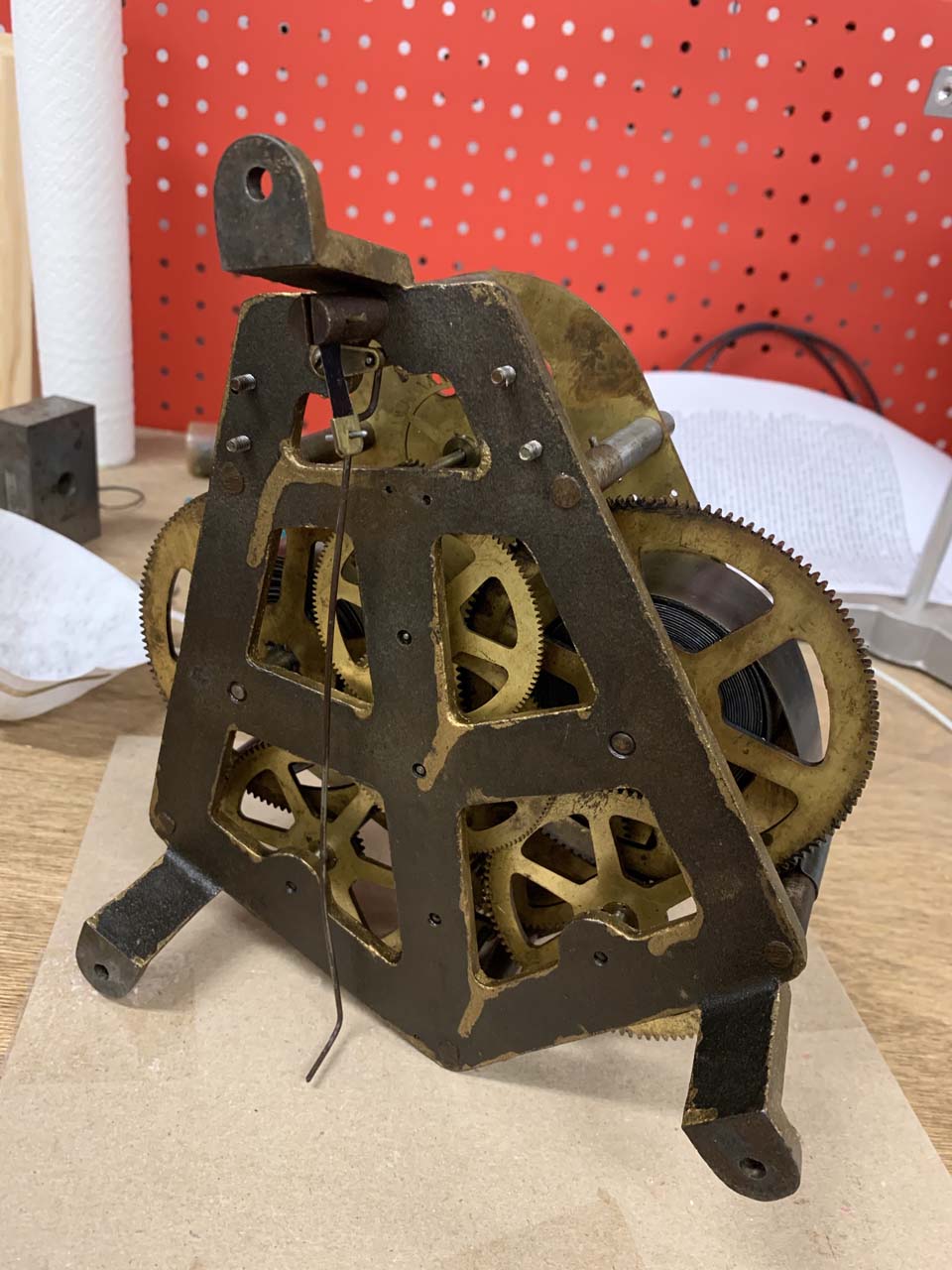
Another way the clock is unusual is the back plate – it is thick cast iron rather than brass. Most clocks use brass for the movement plates and steel for the pivots. In addition to looking pretty, this is done for a reason – brass and steel are chemically compatible for wear. Steel on steel can be problematic. This is mitigated to a large degree with oil, and this clock obviously worked fine for the first hundred years of operation, so clearly it can work just fine, but it’s an unusual setup.
When I originally serviced this clock I approached it the way I approach any clock. The basic steps are to ultrasonically clean, polish the pivots, repair any wear with bushings, reassemble, and oil. Bushings get polished as well with a smoothing broach. If a pivot hole isn’t sufficiently worn to require a bushing, I normally just scrape out any leftover gunk the ultrasonic cycle missed with some peg wood.
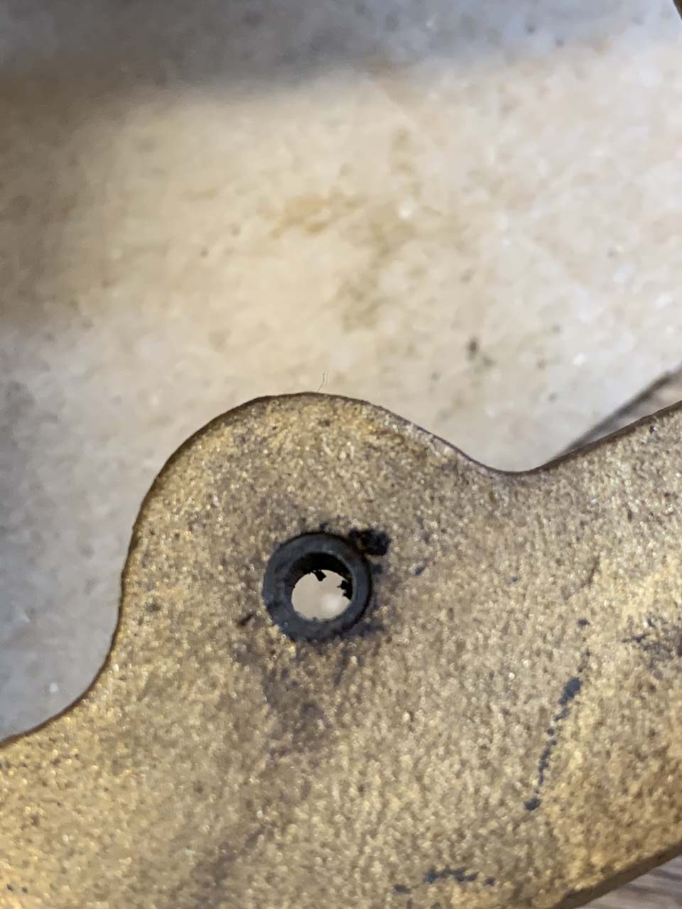
At first glance the oil on the winding gear pivots was a little dirty. This surprised me. Also, the pivots in the back side of the movement looked dry. There was a bit of oil there, but not as much as I expected.
I disassembled the movement to check the condition of the pivots. They looked fine. I checked the verge pallets, and there were a couple minor marks. I don’t believe I polished the verge the first time around, so I did it this time.
Before reassembling the movement, I tried to address the pivot holes in the cast iron back plate. I’m not entirely sure what the best way to approach this would be, but I took some time with some peg wood and got some more junk out. I did this the first time too, but apparently not adequately. I reassembled the movement and added a bit more oil to the rear plate pivots.
The Pendulum
The other thing I wanted to readdress this time around was to add even more weight (!) to the top of the pendulum rod. A quick refresher (more detail in my first post) – with the bob in the center of the adjustment range, the clock ran 5 minutes per hour too slow. Somewhere along the way the movement got altered or replaced, and the pendulum as I found the clock was too long for accurate timekeeping. For aesthetic reasons I didn’t want to just cut the pendulum rod shorter – it already seemed too short for the case, so I opted to add a bunch of weight to the top of the pendulum rod, which increases the speed of the pendulum, allowing me to move the bob down to a reasonable location on the rod.
The clock kept time with the added weight I settled on last time, but just barely – the bob was all the way at the top of the adjustment range. I wanted to drop the bob to the middle of the adjustment range if possible.
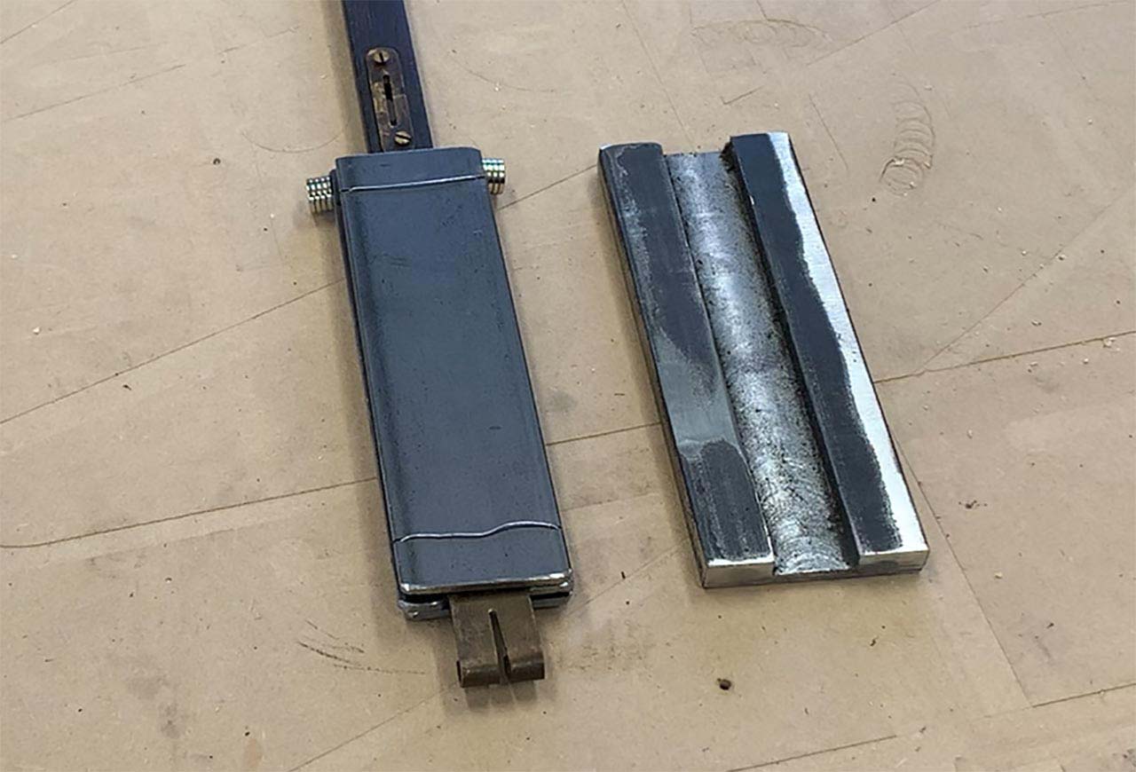
Space behind the movement is limited, so the weight needed to go mostly to the side of the rod. Last time I used multiple layers of 1/8″ thick 1 1/2″ wide steel bar. This time I used a piece of 3/8″ thick by 2″ wide bar.
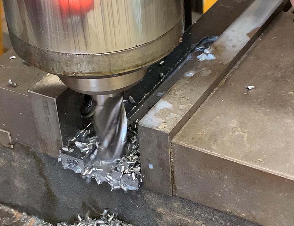
The pendulum rod is just under 3/4″ wide. A 3/4″ end mill was almost a perfect fit. I cut the slot in two depth passes, leaving the slot just shallower than the thickness of the pendulum rod.
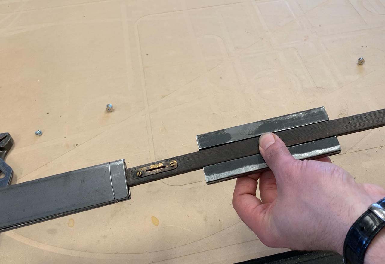
Here you can see the original weight arrangement the clock ran with for the last 5 months and the larger machined block.
I didn’t want to do anything to irreversibly alter the pendulum, so I decided to clamp the weight to the pendulum rod with a piece of the same 1/8″ thick 1 1/2″ wide bar I used previously.
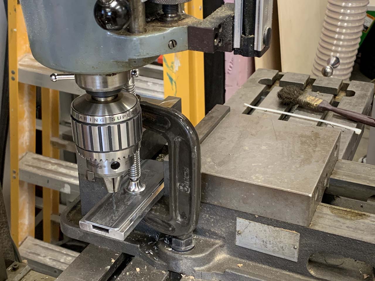
I drilled and tapped holes (including one broken tap) for screws to clamp the pieces together. Other than the broken tap, it turned out great. Even the casual eye may notice something strange about my drilling setup in the photo above. A real machinist would have measured offsets from the edges of the parts and calculated the hole positions for drilling. As I am not a real machinist I am free from those constraints, so I took the “close enough” expedient alignment method of eyeballing it and using a C-clamp to hold the parts in position while I drilled the pilot holes. The parts were just long enough for me to be able to flip the part around to drill the second side without having to reclamp the C-clamp position.
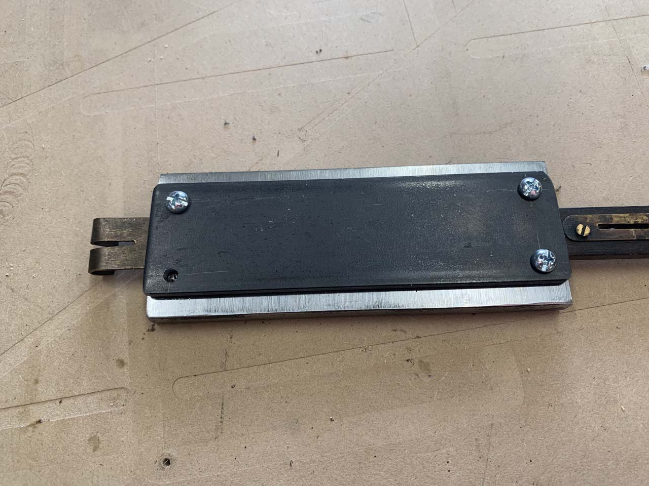
This is a really strange situation – the top end of the pendulum weighs more than the bob.
Pendulums need to be plumb to run correctly. This means the suspension point needs to be directly over the center of mass, otherwise the pendulum will do funny things. When I reassembled the clock, the pendulum was arcing in the horizontal direction – the leading edge arced toward the back of the case. I bent the hanger slightly backward to better align the center of mass under the suspension spring and it started running normally.
I timed the clock and put the dial and hands back on. Amplitude seems to be better than it was, so hopefully I’ve addressed whatever issue I didn’t handle adequately on my first go at the movement. It’s a little unsatisfying to not find a smoking gun, but much of success or failure in clock repair comes down to little problems adding up. Hopefully my second look will give this guy another decade of good service before I need to look at it again.
Update 8/19/20
I have run this clock for about 4 months since I wrote this post initially and I think I know why the clock was stopping – I wasn’t winding it enough. Most clocks need about one turn of the key per day. Some need two turns per day. I wasn’t sure what this clock needed and I didn’t really want to fully wind these ridiculously massive springs as breakage may destroy the clock, so I guessed how much it needed and wound it about 16 turns per week. That isn’t enough – for the last 4 months I have wound 24 turns per week and as best as I can tell the spring is staying wound to about the same degree. It’s all part of the fun of being an antique detective.
One reply on “Lockwood Almquist Revisited”
Thank you for your article… I just got a hold of a Lockwood & Almquist Co. Clock… it’s very large… 19×19 and 6in. deep with a large round dial. It has the same 2 large main spring setup… your article was just about the only information I could find on this clockmaker… Do you have any more information about this company? I thought I had read somewhere that the movements were made under contract by Seth Thomas…. Anyways I wanted to reach out and thank you… Gene