
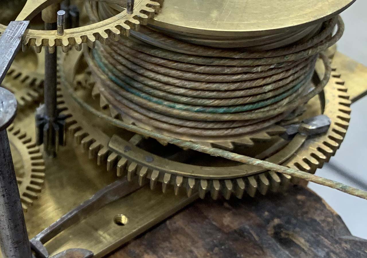
I have been working on an early American tall case clock. The click spring on the strike drum is pretty shot – the finger that makes contact with the click is worn down and the spring is bent. Winding the clock causes the click to jump behind the spring, breaking the ratchet action.
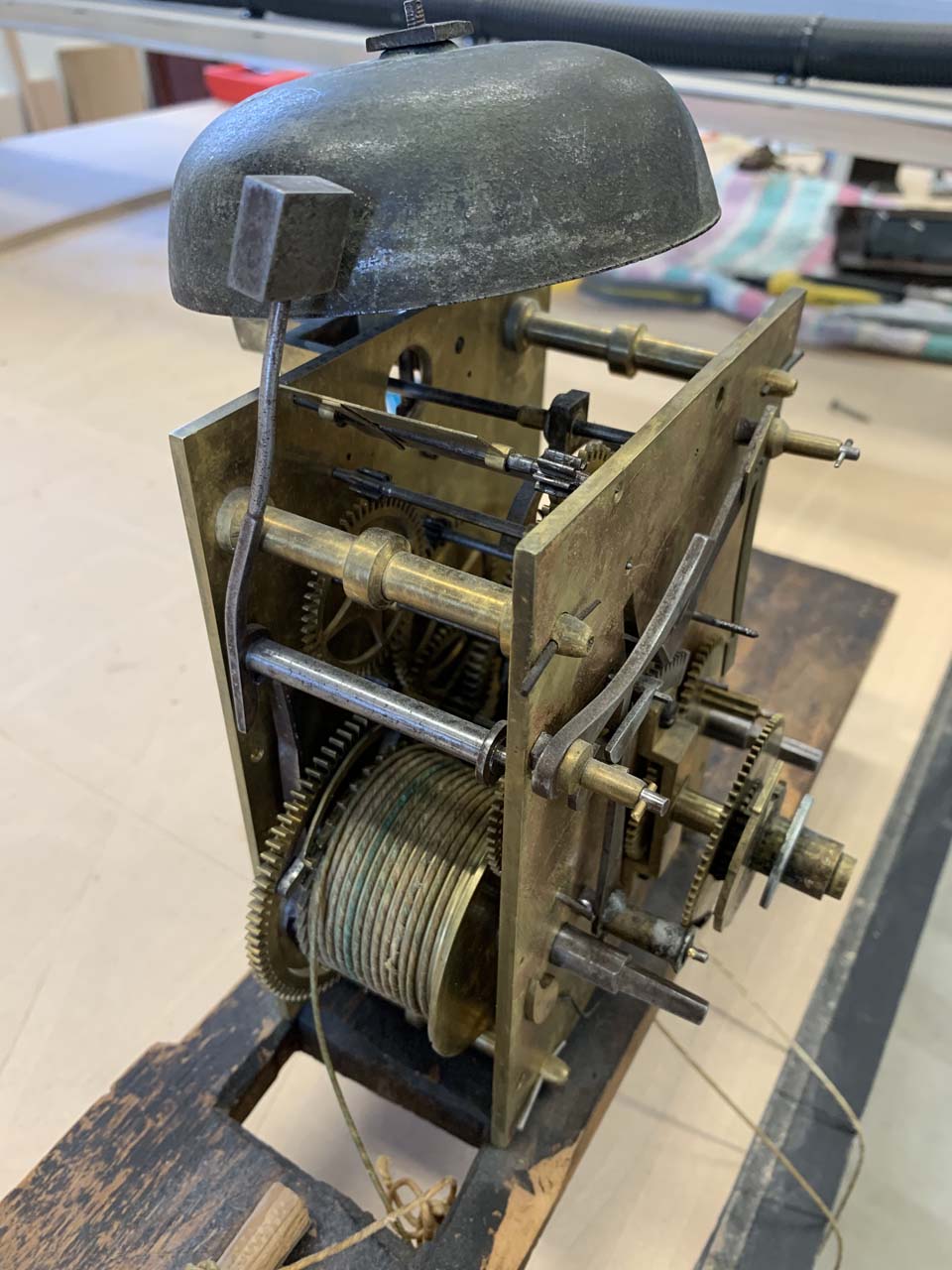
Clocks this old were largely hand-made. Gears were cut with a machine, but much of the other work was done by hand. This click spring was filed out of a sheet of brass and riveted onto the gear. I think the spring was poorly designed – it is fairly tall which gives it its pushing force, but it is also very thin, meaning it bends easily in a direction I don’t want it to bend. For the replacement spring I wanted to make it out of a thicker sheet of brass.
My interests run the gamut of technology – from clocks built before the industrial revolution to modern manufacturing techniques. I wanted to see if I could make the replacement part using my CNC router.
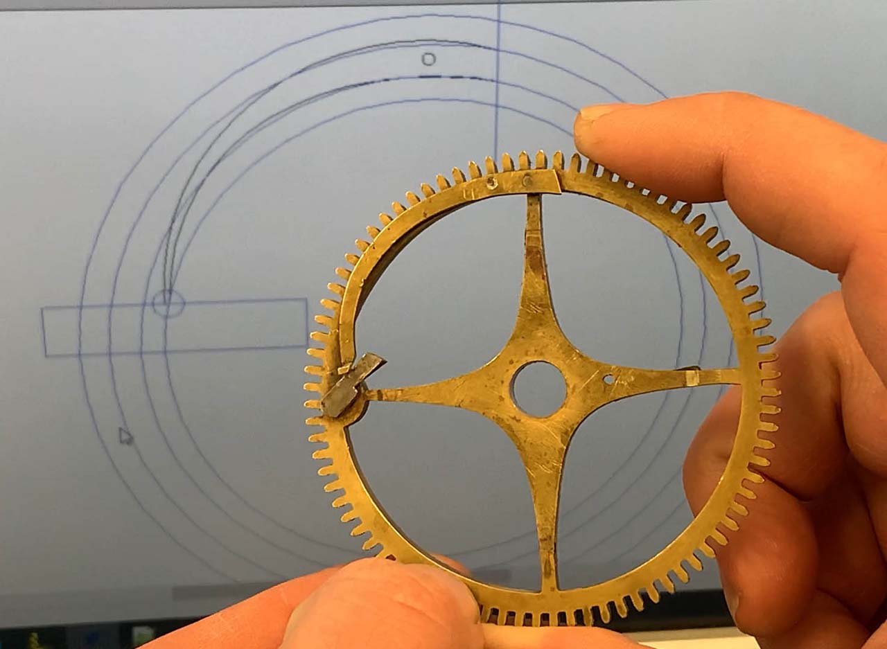
I measured the gear and made a crude model in my CAD software. The outer circle is the outside of the teeth, the next two rings are the solid ring of the gear, and the inner circle is an approximation of where the contact point between the click and the click spring needs to be. I drew the spring profile with a couple Bezier curves.
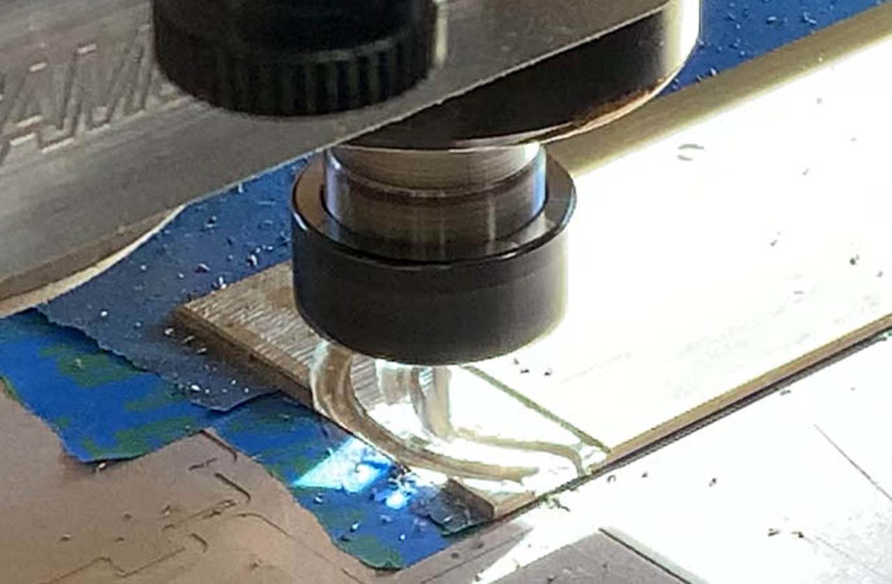
My CNC router is primarily a wood-cutting machine, but it can also cut soft metals like aluminum and brass. This was my first attempt at brass.
There is quite a bit to the math of feeds and speeds and cutting geometry. This matters to varying degrees depending on what you’re trying to do. A feed rate that is too fast can break bits. Too slow and the heat of the cut isn’t evacuated in the chips and the bit overheats and dulls. If I was making a thousand of these, this stuff would matter (and I probably wouldn’t be making them on a woodworking CNC router), but for a one-off experiment, taking shallow passes and going slow is the path to success.
The prescribed bit for cutting brass and aluminum is called an “o-flute” bit. This is a one flute bit with a curved gullet that is designed to remove material without the chips sticking to the cutter.
I started with a 1/4″ bit, thinking that would likely be more forgiving than starting with something smaller and more fragile. In larger work, I think I can probably take passes up to 0.200″ thick, but since these bits cost about 30 bucks, I decided I had more time than money and took 0.006″ passes. When I ran the job it was almost comically slow – it took about 6 minutes to shave off 30 thousandths on a 1″ x 3″ area, but I didn’t break my bit! Part of the slowness was the stepover parameter – how far the bit moves over for each pass. The tool default was 10%, meaning that on a 0.250″ diameter tool, the tool only moved over 25 thousandths per pass.
The profile passes were similarly shallow, but unlike the clearance path, the bit has to cut full width to go around the part. This went fine for the most part, but it did leave a little nub of brass on the click spring because the bit broke the part away from the stock.
The finished click spring is a little rough looking, but it’s the shape and size it is supposed to be. I clamped it onto a piece of metal to get a feel for how strong the spring was. Since I wanted to change the design of the click spring, I needed to determine experimentally the right width of the spring. The first attempt was pretty stiff.

Back in the CAD software, a minute change to one of the Bezier curves made the spring slightly thinner in width. Small changes can make big differences in spring strength, so I wanted to go easy for the second attempt. Buoyed by my relative success the first time around, I decided to shift down to a 1/8″ bit so I wouldn’t waste as much material. With new toolpaths in hand, I headed back to the router.
The 1/8″ diameter bit is a better choice for the profile cut – a smaller cutter means less cutting force on the part, so in theory the chances of me firing it across the shop would be lower. However, a 1/8″ bit removes a lot less material than a 1/4″ bit, so the pocketing operation would take longer this second try.
The difference between the first and second parts is hard to see without them being side by side. I clamped up the new spring to test the spring force and this time it felt about right.
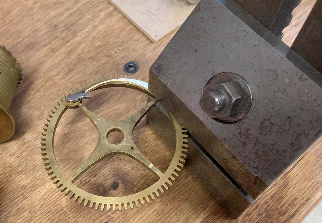
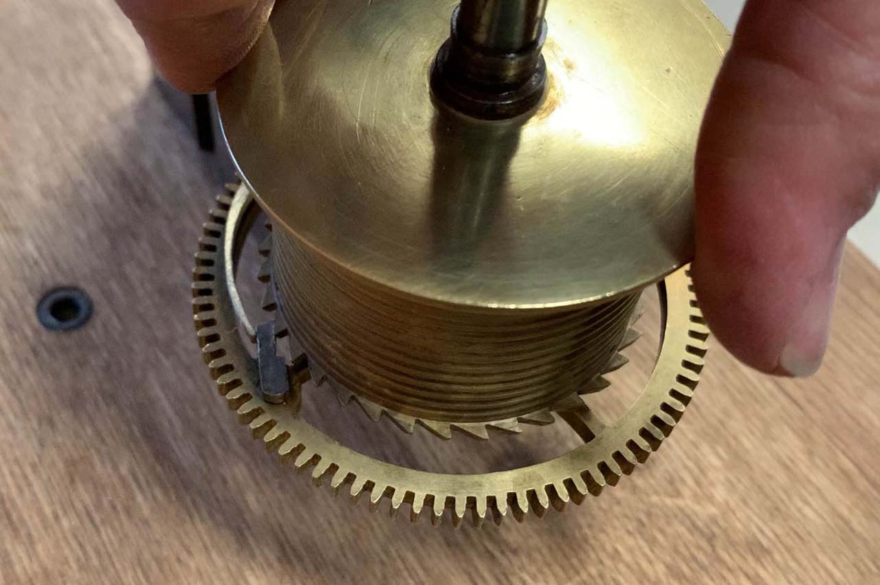
The click spring is pinned to the gear. The old spring was pretty easy to remove – the pins had worked themselves loose in the 170 years this clock has operated. After removing the original click spring, I mocked up new spring to see if this was going to work. Normally Murphy’s Law would assume that it would take three guesses to answer a yes or no question, but Murphy must have been busy – spring #2 was almost perfect.
I probably spend too much time agonizing about non-performance-affecting elements of clock work. I have no problem putting the work in to make a clock mechanically sound, however the tedious stuff like polishing wheels is not a source of joy for me. Out of the router, the surface finish of the new click spring was pretty rough. I sanded it with 120-grit sandpaper and then hit it with some Simichrome polish with a wheel in my rotary tool, and I think it looks good enough to be worthy of the clock.
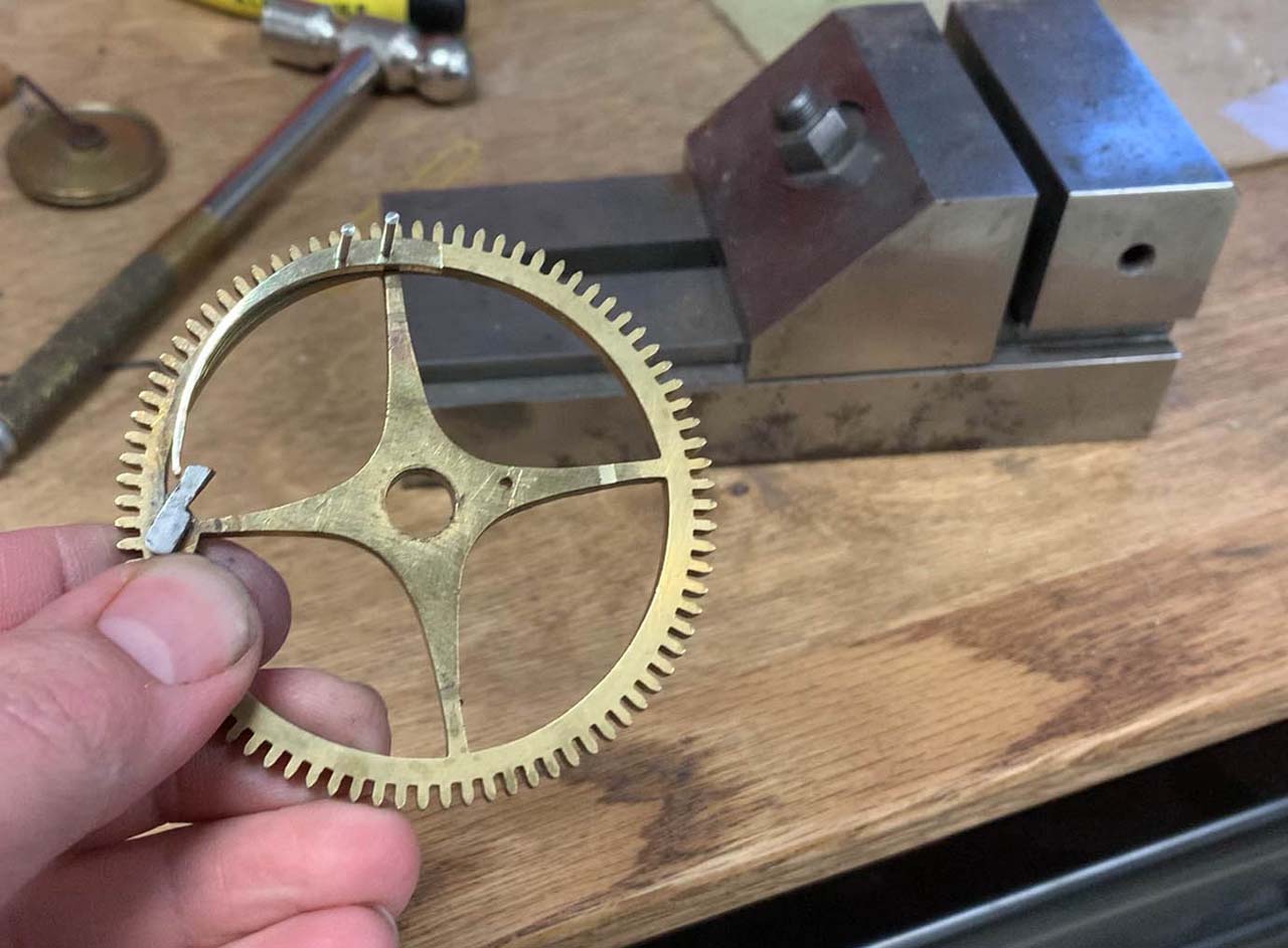
With the spring and wheel still held in the vise, I scratched the outline of the click spring onto the wheel. I re-clamped the spring and wheel in the vise to allow access to the holes. I wanted to reuse the original holes in the wheel, so I used them as a reference and drilled through the new click. I reamed the holes to size using a cutting broach. I made the holes in the click slightly larger than the holes in the wheel because I wanted to mount these with taper pins, with the wide side of the pin coming into the click spring. After a few minutes of fussing around, I had a good product.
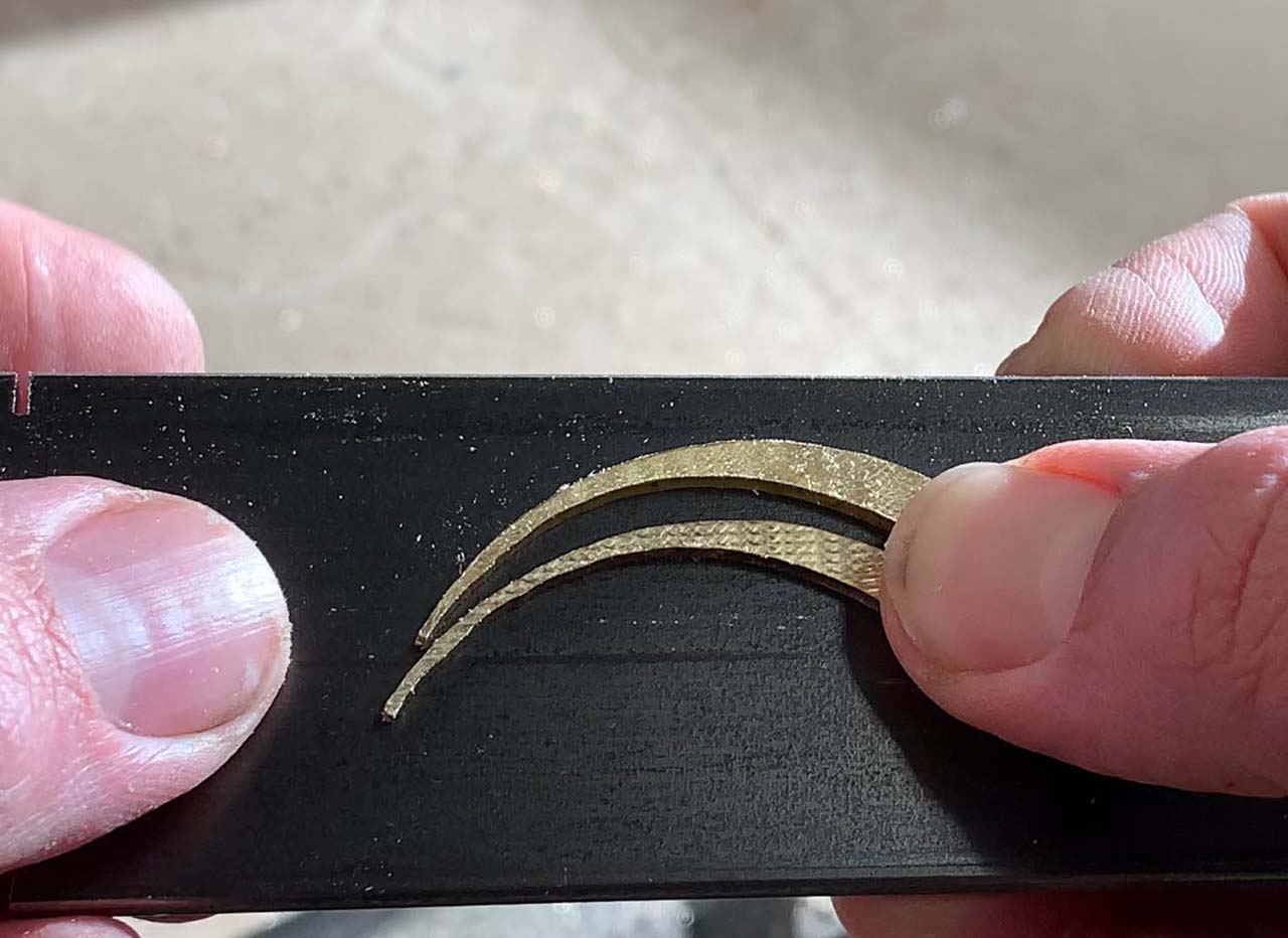
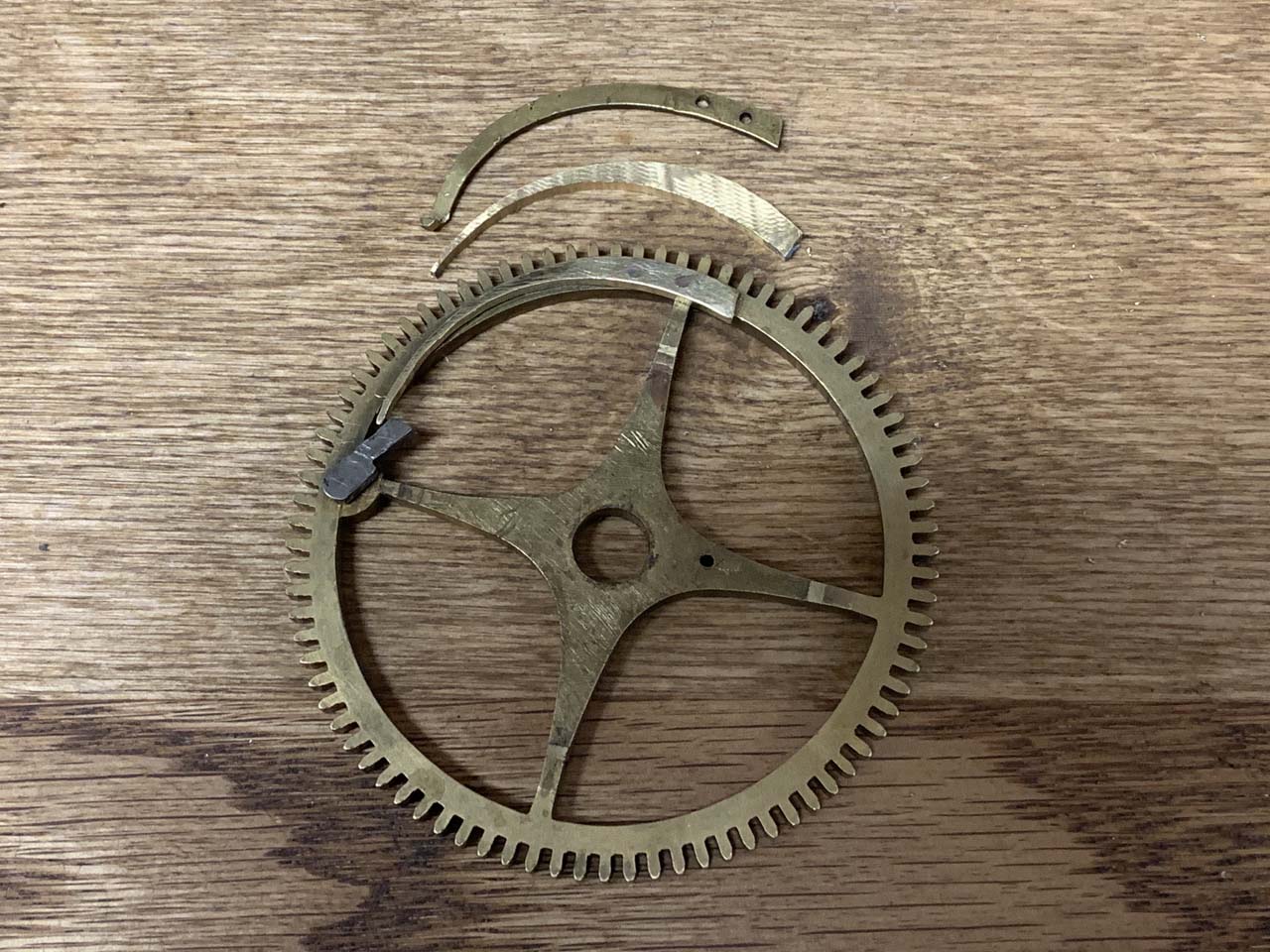
I cut the pins to size using a cutoff wheel in my rotary tool. The picture below shows the original click spring (top), my first router-cut part (middle), and the second spring riveted onto the wheel.
I have no doubt this was the long way to solve this problem. I could probably have traced the old click spring, cut it out with my scroll saw and been done in 1/2 the time, but I learned a lot doing it this way, and any project where you get to use a power tool is a good project. That and if I ever work on another identical tall case movement needing exactly this geometry of a click spring, I’ll be ready to go.