Most of my repair work has been on smaller pieces, but I’ve done a few full-sized clocks lately, and have needed something more convenient to rig and test movements in process. Previously I set them back up in the case, which creates challenges accessing the back of the movement.
I got some ideas from looking at other commercially available stands and then hit the scrap bin. These aren’t rocket science, and I have a substantial pile of odds and ends from previous projects to make use of. We’re still under Coronavirus lockdown, so I wanted to see how little extra I had to procure to make this happen.
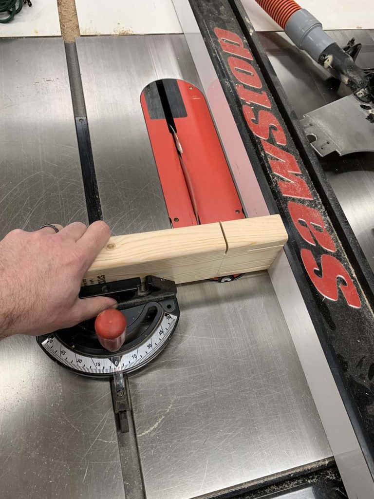
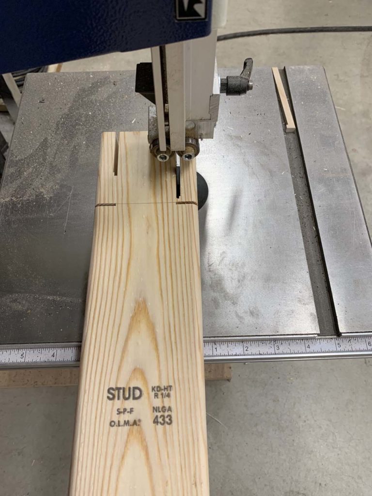
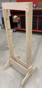
The frame is pretty simple – 2 x 4 verticals and 1/2″ plywood cross members on the top and bottom. The width of the stand is pretty arbitrary – I settled on 20″ wide which should cover pretty much everything. The depth is more critical – it needs to be narrow enough to not get in the way of the hands in front and the pendulum in back. I cut down the sides of the 2 x 4 verticals to 2″, giving a 2″ gap between the cross members and about 3″ total depth.
I cut the legs out on my CNC router and added a couple of leveling feet.
I have been learning many things in my horological pursuits these last few years. I’m not new to building things, and I’m blessed to have a fairly well-equipped, if small, shop. One thing I wasn’t expecting to learn was to navigate the challenge of having good mess-free photography of shop projects in a working shop that is, well, a bit messy. I don’t think my shop is any messier than the typical shop, but the normal workings of making things – tools and project bits – tend to stay out on surfaces while the project is underway. This isn’t a huge problem for pictures of small items – it’s easy to frame the camera shot around the sawdust or tools, but larger projects like the stand require a shot with a wider field of view, which in the case of the center photo below, includes the open door on one of my benches revealing my high-tech cardboard box holding my shop rags. Conveniently cropped out of the frame on top of the bench is the half-reassembled remote control car I was epoxying back together for my son.
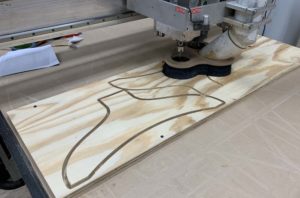
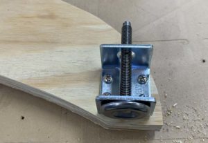
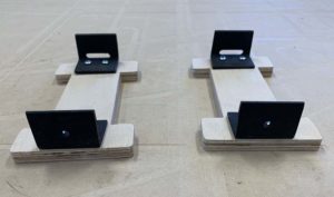
While the basic stand is straightforward, the movement mount took a little more thought. It needs to be able to accommodate a wide range of sizes. Back to the CNC router, I cut a couple dog bones that can slide to handle whatever size movement I’m working on.

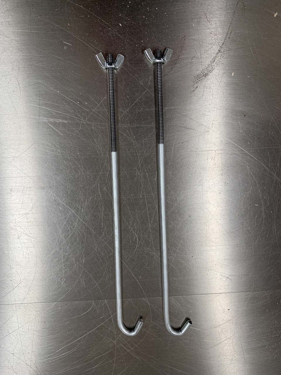
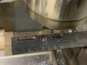
I made a couple long J bolts by threading a piece of 3/16″ zinc plated steel rod. Please excuse the crudity of the J bend – I don’t own a metal bending jig and made them with a vise and a couple pairs of pliers. I threaded the rod by putting the rod in a drill chuck in my mill and holding the thread die. The machine did the turning, I just held on.
The J hooks attach to the stand dog bones with a pair of angle pieces. I milled a slot in the top piece to allow for some positional adjustment, as some movement pillars have decoration or other obstructions that wouldn’t be able to be worked around with a straight up and down clamp arrangement.
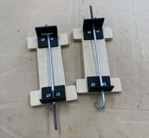
The rods are long enough so the clamps can be tightened at the bottom of the dog bones which is easier to access than trying to reach between the stand cross members.
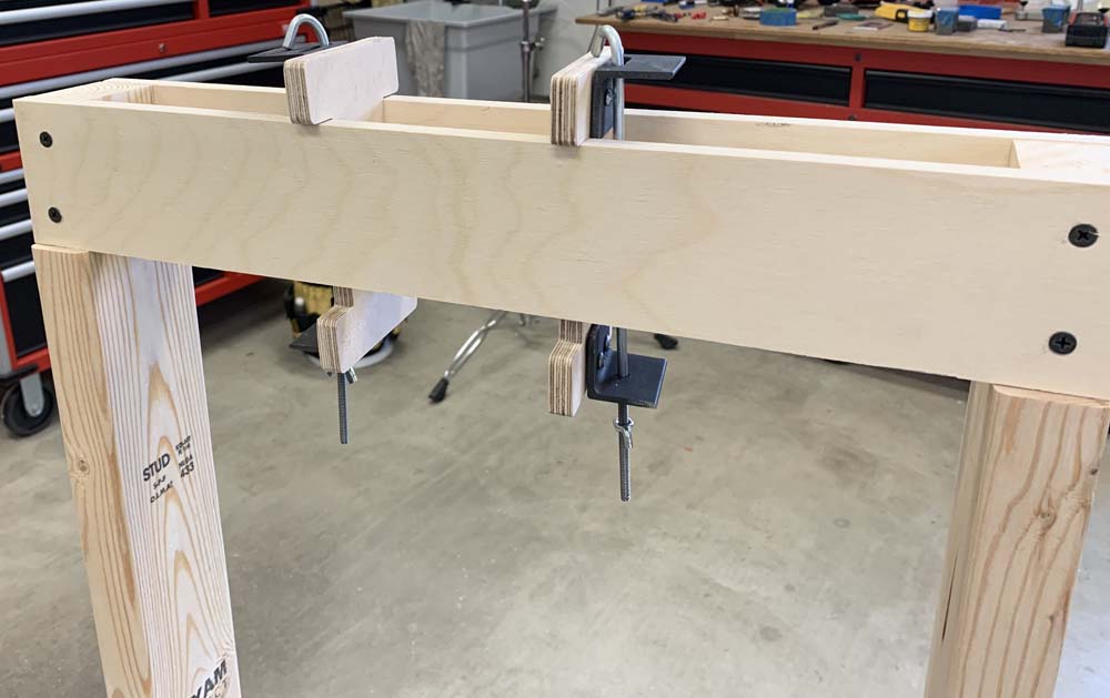
I left the dog bones a little bit taller than they needed to be to clear the cross members. My original plan was to attach T nuts to the bottoms of the dog bones where hand screws would come up through the bottom leg of the dog bone, through the T nut, and then press on the cross member to clamp it in place. I may still do that eventually, but due to the magic of tight-tolerance machines (CNC routers are amazing), the dog bones have almost the perfect amount of friction against the cross members that they are plenty secure.
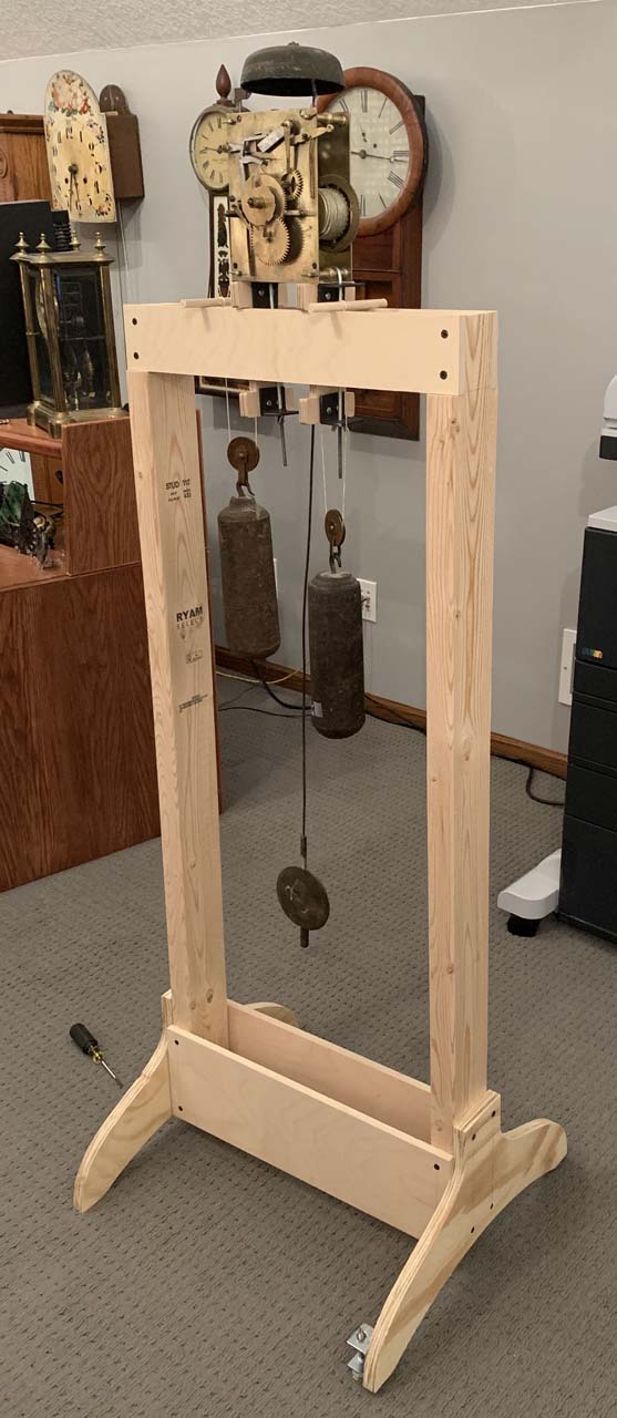
On the stand is a tall case movement from the first half of the 18th century – possibly 1725 or so. The open design of the stand allows the free end of the weight cord to be moved around for clearance.
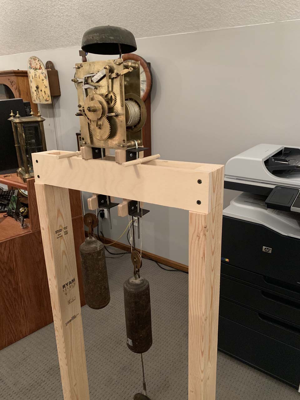
It’s a bit hard to tell from the picture, but the weight cords on this movement come off the left side of both the time and strike winding drums. The time drum (right side of movement) works out well with the free end of the weight cord to the right of the movement, and the time weight hangs almost directly below the time drum. Since the strike drum (left side of movement) winds in the same direction and therefore the cord comes off the same left side of the drum as the time side, the strike weight actually runs to the left of the movement drum, and the free end of the strike cord is a few inches on the left side of the movement. For clearance, I actually rotated one of the dog bones so the metal brackets wouldn’t be in the weight path.
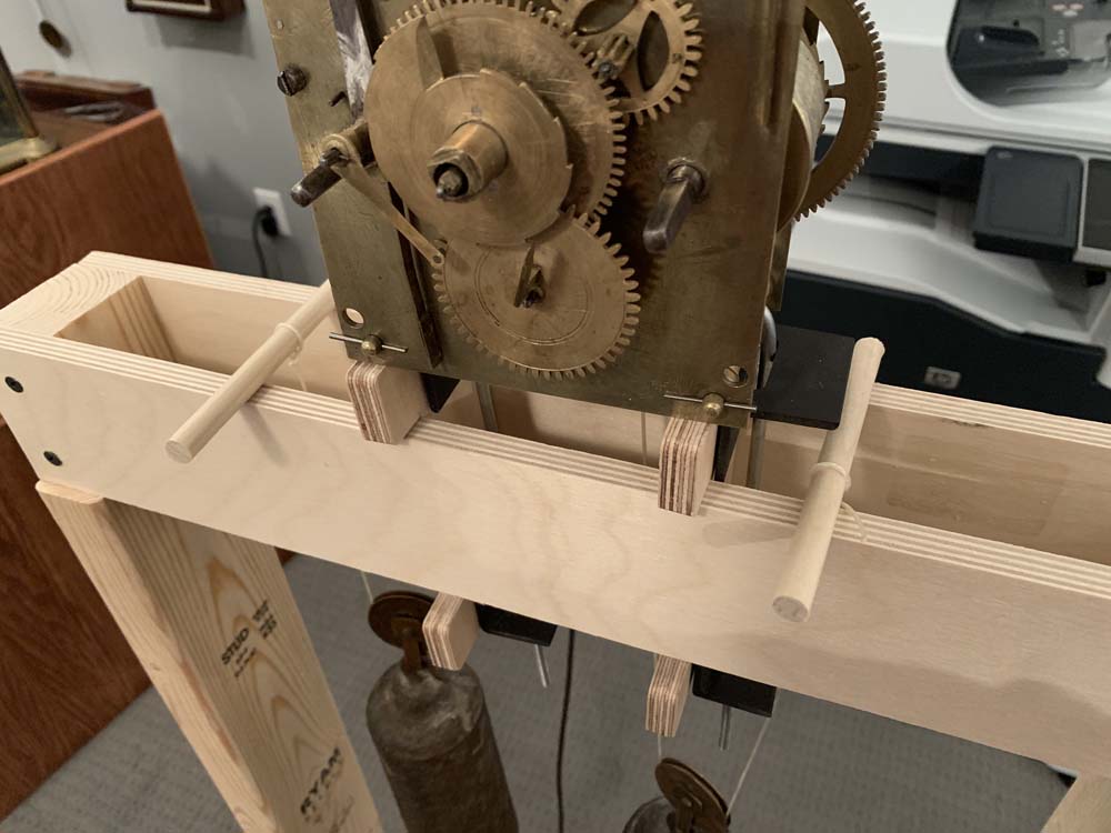
The free ends of the weight cords were tied around a couple dowels. This movement mounts to a seat board and the weight holes are in the seat board. This stand should accommodate putting the seat board on with the movement, but I wanted to get a bit more clearance on the movement, and so improvised a bit. The thickness of the movement stand was calculated so the pendulum is outside the stand to the back, the weights fall through the middle of the stand, and the hands can rotate unobstructed in front of the stand.
This is an interesting and very old movement. In addition to the usual counting of the hours on the bell, this clock strikes the half hour as well. The date is shown through an aperture on the dial, driven by the gear at the bottom front of the movement with a metal flag sticking out. More on this fascinating clock soon!
10 replies on “Building a Clock Movement Test Stand”
Nice stand. How much would you charge to make one?
I hadn’t planned on selling these, but could maybe work out something. I will contact you and see what parts you need.
I’d like to have one, email me at wayne120002002@yahoo.com
Nice stand you made. I don’t have enough tools to do what you did, but, I think I will be able to make one, too. Thank you for the great ideas.
I was hoping to turn my grandfather clock into a skeleton clock by mounting all of the movement, including chimes, on a rack that functions like the one that you show, but looks has a finished design.
Your thoughts?
Thank you,
The complexity of a nice mechanical movement are worth looking at, for sure. There are two things I would suggest you consider:
– The stand must be suitably rigid so that the clock doesn’t lose energy from the pendulum swing by transferring it to the stand. The weight of the pendulum determines how challenging big of a deal this is.
– Dust. You may want to consider an enclosed case that has windows that reveal the mechanics rather than just an open-air stand.
This is pretty much what I was looking for. I’m like some of the others in that I don’t have the all the woodworking equipment and don’t want to buy it just for this project. Being that it’s winter in the northeast, all the wood particles in our finished basement is also an issue. So I thin there’s some call for a kit of precut parts… if you want my opinion. I’d be another interested person to add to the list!
Thank you for the excellent demonstration. I do not have the shop tools you have, but I was able to build a reasonable facsimile based on your plan and ideas. I had to adapt to my hardware store not having some desired parts, but it went together in 3 hours – level and stable.
Let me know if you start selling your grandfather clock test stands.
Your hold down bolts look similar to auto battery tie down bolts. Not too expensive and ready to use.