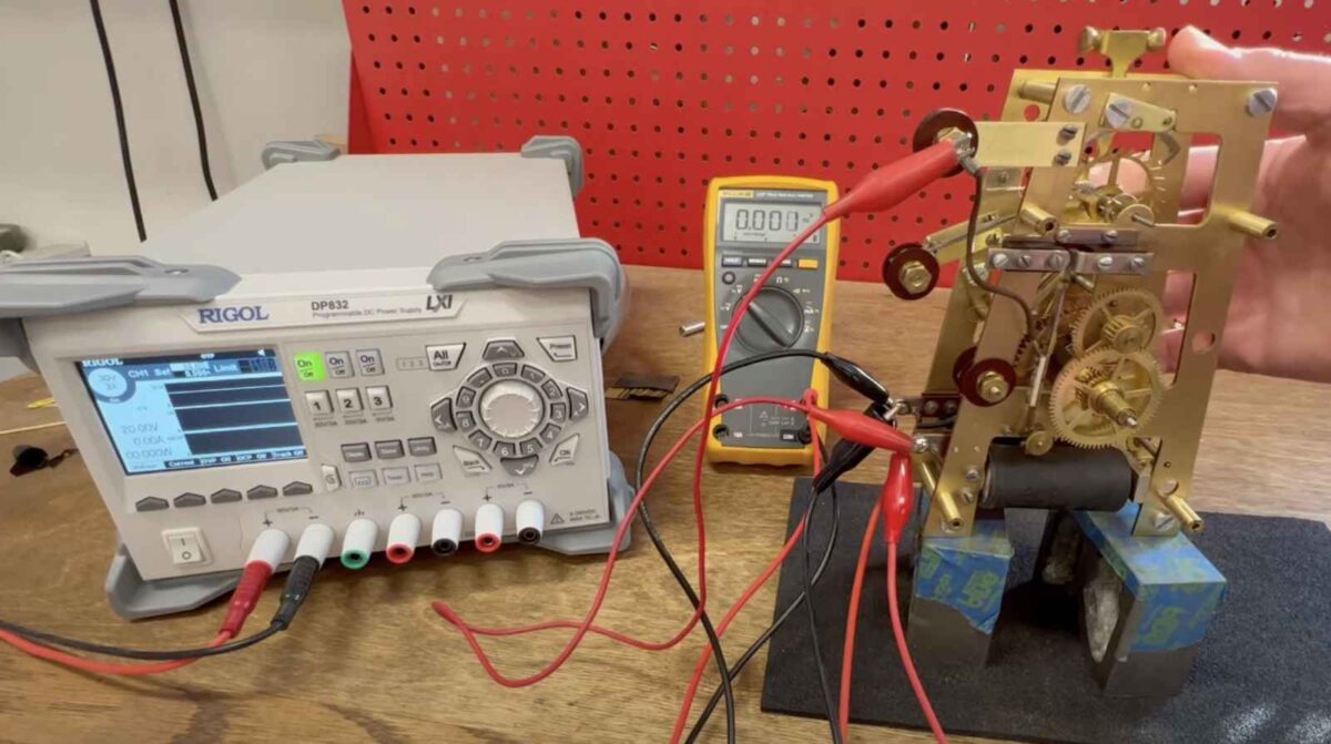
Electric clocks span two worlds – the mechanical world of gears and escapements, and the electrical world. If you desire to work on electric clocks, one tool you will need to own and know how to use is a digital multimeter, sometimes called a voltmeter.
A digital multimeter is not expensive and you don’t need a particularly fancy one. At a minimum, your meter needs to be able to measure AC volts, DC volts, resistance (sometimes called ohms or with the Ω symbol), and continuity.
Important note: Electricity is dangerous. Never touch a circuit unless you understand the level of power present (if any) and have measured it yourself. In a clock context, voltages less than 30V either AC or DC are safe to touch. For voltages higher than this, deenergize the circuit before working on it.
Types of Electricity
AC Volts
AC – short for alternating current, is the type of power that comes out of a receptacle in your home. In the USA, our power standard is 120 volts (V), and the direction of current flow alternates back and forth 60 times per second. This type of power is used for electrical distribution because it enables the use of transformers which help send power over long distances efficiently. Transformers can be built to either raise or lower the voltage.
DC Volts
DC – short for direct current, is the type of power that a battery makes. Current always flows in the same direction. DC power was discovered first and is useful for many things, but it cannot be sent through a transformer, so it is typically used inside devices.
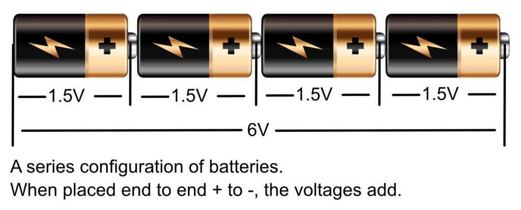
An alkaline battery produces about 1.5 volts (V) when fully charged. Batteries can be connected in series (end to end + to -) to increase the voltage – e.g. a 4 battery system would produce 6V.
Converting AC power to DC power is relatively simple using a semiconductor device called a diode. DC voltage can be converted to AC voltage either by using a DC motor that drives an AC generator, or using electronic means that are out of scope of (and much later in history than) our electric clock work.
Circuits, Continuity and Resistance
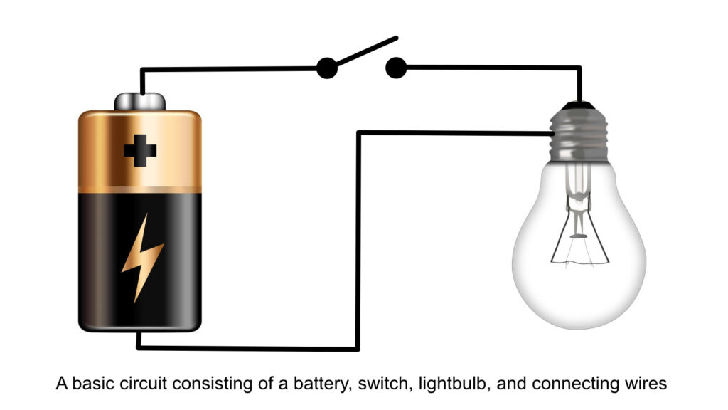
For any electricity to flow, there must be a continuous path for the current that leaves the power source by one terminal, goes through the electrical device that does the work (the ‘load’) and then returns to the power source by the other terminal. For example, a flashlight’s circuit has the following components: A battery, a switch, a lightbulb, and connecting wires.
Determining if the battery is good requires a DC voltage measurement; determining if the rest of the circuit is good requires a continuity or resistance measurement.
Continuity
The word continuity means that a thing is continuous. A continuity measurement in an electrical context determines whether something is electrically continuous. This is a qualitative thing – something is electrically continuous if there are no breaks in the wire or other components so electricity can flow. If there is not continuity, no electricity will flow.
Referring to our flashlight diagram above – as shown, this circuit does not have continuity, as the switch at the top of the diagram is open. In this state, no electrical current will flow, the lightbulb will not light, and the battery will remain fully charged. If the switch is closed, the circuit becomes continuous and electricity will flow, transferring power from the battery into the bulb, and the battery will begin to discharge.
Resistance
Resistance is a quantitative measurement of a circuit’s ability to allow power to flow. This uses the unit of measure called an ohm, which is indicated by the ‘Ω’ symbol. A circuit with a high resistance will allow only small amounts of electrical current to flow. A circuit with a low resistance will allow a large amount of current to flow.
Looking back at our flashlight diagram, in the open circuit state as shown, this circuit has an infinite resistance – zero power flows. If we close the switch, the resistance of the circuit will drop to a value greater than zero, but a measurable number that depends on the type of lightbulb and the size of wire in the circuit.
Taking Measurements
Measuring Voltage
Note: If you don’t know whether the power is AC volts or DC volts, try both. Your meter won’t be harmed if you measure AC power on the DC setting or vice versa. If you get a zero reading where you expect a non-zero value, switch your meter over to the other mode.
AC Volts
To measure AC volts, set your meter to the AC Volts setting, sometimes indicated with a ~ symbol. Touch one of your meter probes to the first point of the circuit you wish to measure, and touch the other probe to the second point of the circuit you wish to measure. As AC voltage continuously reverses direction, there is not really a concept of positive and negative, so it does not matter which probe you place where. Be careful – in a clock context, the AC voltage you measure will usually be 120V power directly from a receptacle, and this amount of power is dangerous.
DC Volts
To measure DC volts, set your meter to the DC Volts setting, sometimes indicated with a solid/dashed line pair. Touch one of your meter probes to the first point of the circuit you wish to measure, and touch the other probe to the second point of the circuit you wish to measure. Your multimeter will have a red and a black probe. If you place the red probe on the part of the circuit near the positive terminal of the power source and the black probe near the negative terminal of the power source, your meter will show a positive voltage. In a digital multimeter, if you reverse the leads so that the black probe is near the positive terminal of the power source and the red probe is near the negative terminal of the power source, the meter will show a negative voltage reading. This will not harm your voltmeter; the minus sign on your meter will let you know that relative to your probe positions, the voltage is negative.
Measuring Continuity
To measure electrical continuity, DISCONNECT the power source to your circuit before measuring. This is necessary as in continuity mode, your meter uses its own battery to power the circuit while testing. External power will invalidate the measurement and may damage some multimeters. Set your meter to the continuity setting, often indicated by a symbol that looks like sound waves. Place your probes where you wish to test. Polarity doesn’t matter when measuring continuity. If your meter beeps, your circuit is continuous. If your meter does not beep, your circuit has a break somewhere or your probes are not making good contact.
Measuring Resistance
To measure resistance, DISCONNECT the power source to your circuit before measuring. This is necessary as in resistance mode, your meter uses its own battery to power the circuit while testing. External power will invalidate the measurement and may damage some multimeters. Set your meter to the resistance setting, often indicated by the ‘Ω’ symbol. Place your probes where you wish to test. Polarity doesn’t matter when measuring resistance. Your meter will display the amount of resistance in ohms. If there is an open circuit, your display may show “OL” or overload, which means the circuit has an infinite resistance. In this case, overload isn’t a bad thing and won’t harm your meter; it’s just telling you the resistance is higher than the meter can measure, which in the context of clocks means something is broken or not connected.
Which measurement do I use and what does it mean?
In clock work, we are rarely concerned with quantitative measurements – it makes little difference if the power supply is 23 volts or 25 volts; usually we need to measure qualitative things that fall into two categories: Is power getting where I want it to (voltage measurement), or is the device I’m testing good or bad (continuity measurement).
One other thing to keep in mind: clocks may use power or perform a function (e.g., a self-winding clock may only do so for a few seconds every few minutes), so in many cases, you need to not only measure in the right way, but at the right time.
I created an extensive YouTube series covering the restoration of a Standard Electric Time master clock. I encourage you to watch the entire series as I spend considerable time working through the process to trace and understand how the clock works. In the first part of the series I demonstrate the types of measurements described above.